Graphic: Chapter Add Additional Target Systems for anynode TechNote Request Router

Add Additional Target Systems

In this chapter, we will demonstrate how to add an additional anynode as a third target system to an existing Request Router configuration with two anynode instances.

You can later add more anynode instances as target systems. In our example, we have already configured two anynode instances and now want to add a third instance.

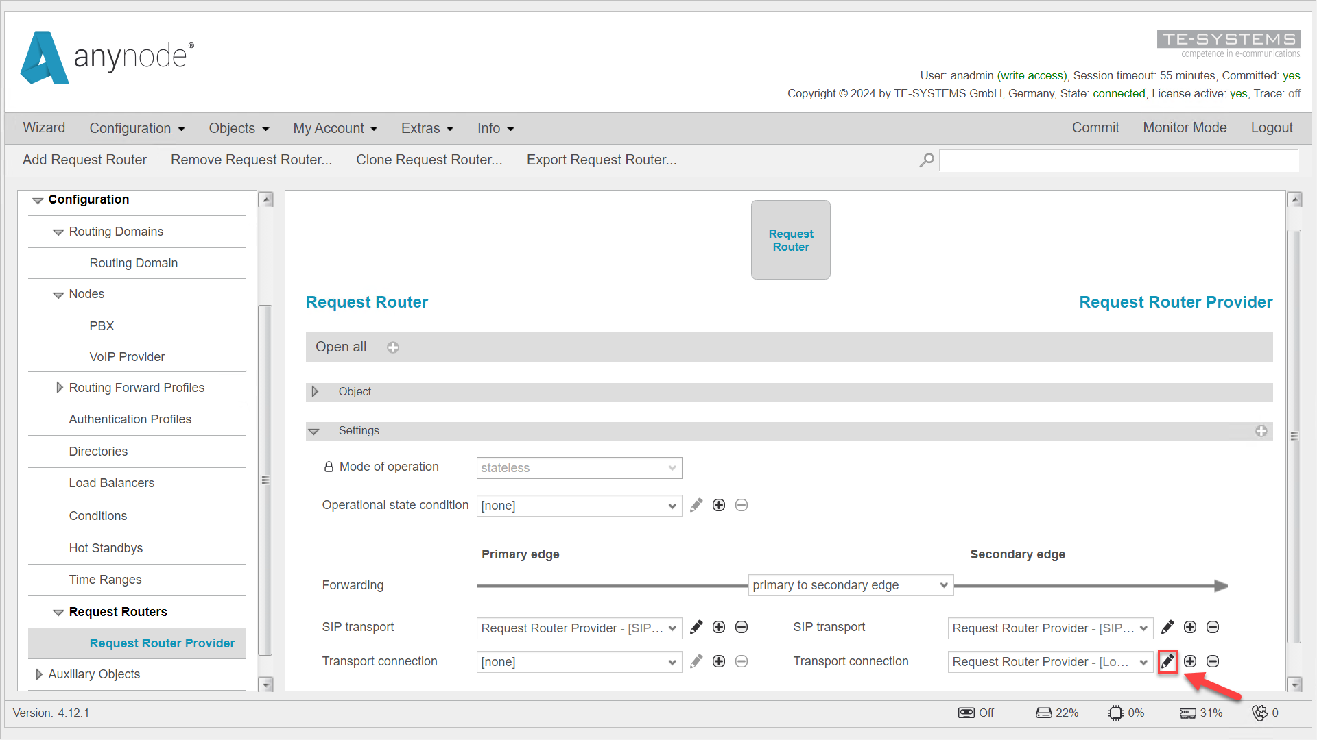
Navigate to the relevant Request Router in the left menu. Click the pencil icon next to the Transport Connection under the Secondary Edge. This will take you to the Load Balancing Connection object.

Screenshot: anynode – The Software SBC frontend with request router primary edge and secondary edge settings overview. Screenshot: anynode – The Software SBC frontend with request router primary edge and secondary edge settings overview.
anynode – The Software SBC frontend with request router primary edge and secondary edge settings overview.

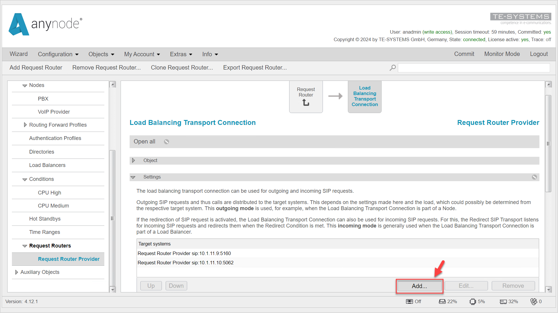
Go to the Target Systems listed under the Settings tab, where the calls from the Request Router are distributed.

Click Add.

Screenshot: anynode – The Software SBC frontend with load balancing connection and target systems overview. Screenshot: anynode – The Software SBC frontend with load balancing connection and target systems overview.
anynode – The Software SBC frontend with load balancing connection and target systems overview.

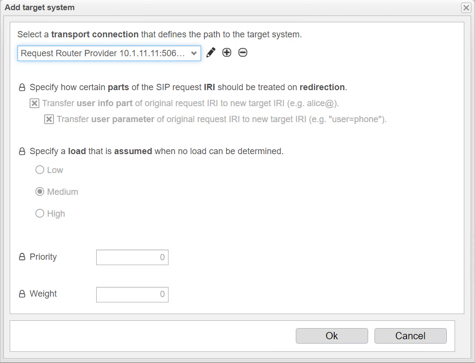
You can configure additional load distribution options at this point.

The option Specify how certain parts of the SIP request IRI should be treated on redirection has no relevance for outbound load balancing requests.

With Specify a load that is assumed when no load can be determined, you can set a predefined load for a target system if the current load cannot be determined with the OPTIONS packets. This specifies the expected load level of the target system. Choose between Low for a low system load, Medium for a medium system load, and High for a high system load.

If you want to configure load distribution based on system load and the load of the target system can be accurately transmitted in the OPTIONS packets to the Request Router Load Balancer, you need to activate Load Reporting on the anynode target systems after completing the configuration. For more information, refer to the Load Reporting section.

Under Priority, you can set a priority level for the target system. This can be useful to determine how likely the system is to be considered in load distribution when no accurate load information is available, as anynode does not receive OPTIONS packets. Targets are grouped by priority, with a lower number indicating higher priority. The range is from 0 to 65535, with 0 being the highest priority. Targets with the highest priority are used as long as they are marked as available.

Under Weight, you can define a weighting factor that determines how the load is distributed among multiple target systems, especially when accurate load information is not available for one of the systems. The range is also from 0 to 65535. The weighting factor determines how often a target is used within a group. For example, if one target has a weight of 80 and another has a weight of 20, the first target will receive 80% of the calls and the second target will receive 20%.

Screenshot: anynode – The Software SBC frontend with add target function in the load balancing transport connection of the request router. Screenshot: anynode – The Software SBC frontend with add target function in the load balancing transport connection of the request router.
anynode – The Software SBC frontend with add target function in the load balancing transport connection of the request router.

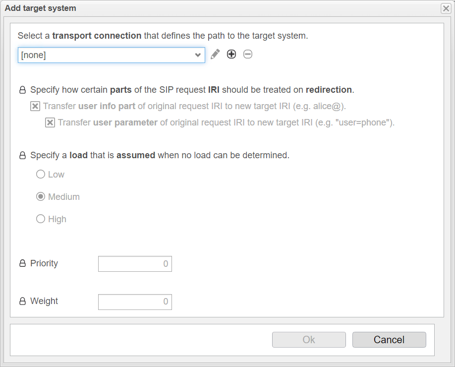
Click the + at the top under Select a transport connection that defines the path to the target system.

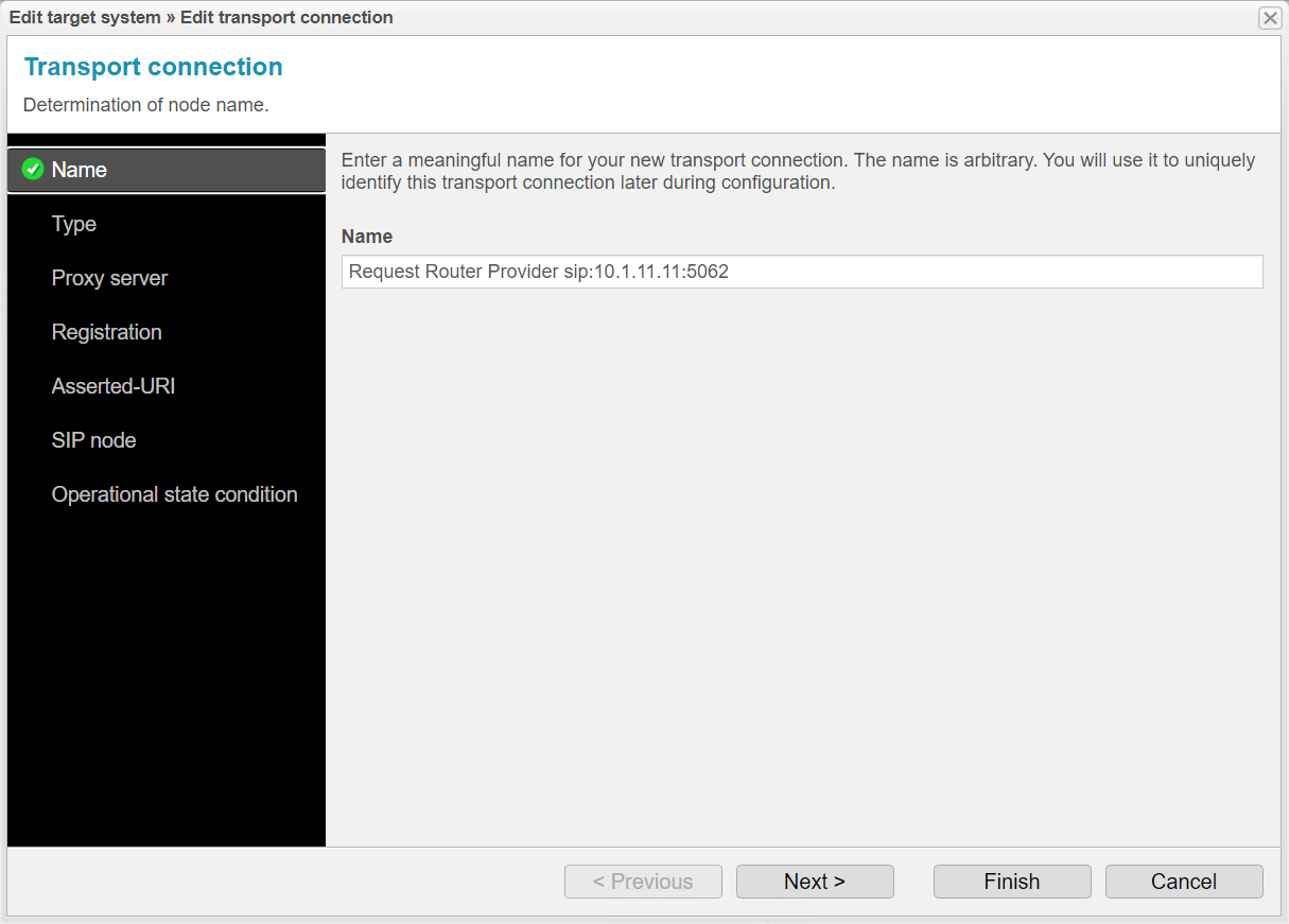
In the assistant, you can assign a name of your choice for the new transport connection and thus for the entry in the list of target systems. Use the IP address of the system you want to add as a target system. For clarity, adjust the name of the new target system to match the names of the existing target systems.

Click Next.

Screenshot: anynode – The Software SBC frontend with add target function in the load balancing transport connection of the request router and name settings. Screenshot: anynode – The Software SBC frontend with add target function in the load balancing transport connection of the request router and name settings.
anynode – The Software SBC frontend with add target function in the load balancing transport connection of the request router and name settings.

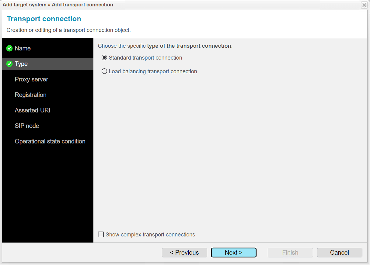
Under Type, there are two options for specifying the type of transport connection

  • Standard Transport Connection refers to the basic connection used for transporting SIP messages between two endpoints.

  • Load Balancing Connection distributes SIP messages across multiple anynode instances to ensure load balancing, scalability, and high availability.

In our example, we want to add another anynode instance without load balancing, so select Standard Transport Connection.

Screenshot: anynode – The Software SBC frontend with add target function in the load balancing transport connection of the request router and type settings. Screenshot: anynode – The Software SBC frontend with add target function in the load balancing transport connection of the request router and type settings.
anynode – The Software SBC frontend with add target function in the load balancing transport connection of the request router and type settings.

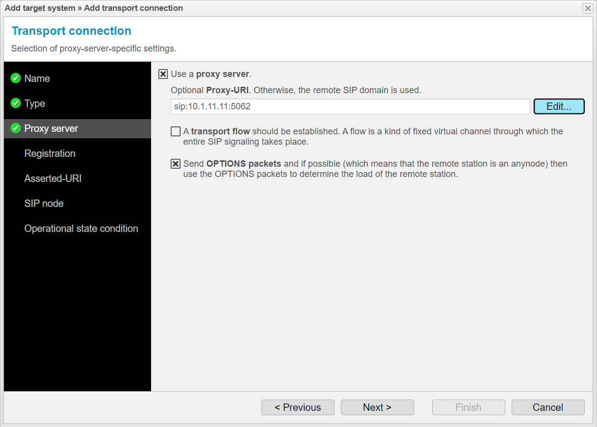
Under Proxy Server, use the IP address of the third target system. We recommend using the Edit... button for assistance. Enter the IP address of the third anynode instance in the Hostname field.

Use the port configured for the corresponding node on the third anynode system.

On the third anynode system, the provider node listens on port 5062, so enter port 5062 here.

Click Ok to finish the input assistance.

Enable Send Options Packets if you want to determine the load of the third anynode instance.

Click Next.

Screenshot: anynode – The Software SBC frontend with add target function in the load balancing transport connection of the request router and proxy server settings. Screenshot: anynode – The Software SBC frontend with add target function in the load balancing transport connection of the request router and proxy server settings.
anynode – The Software SBC frontend with add target function in the load balancing transport connection of the request router and proxy server settings.

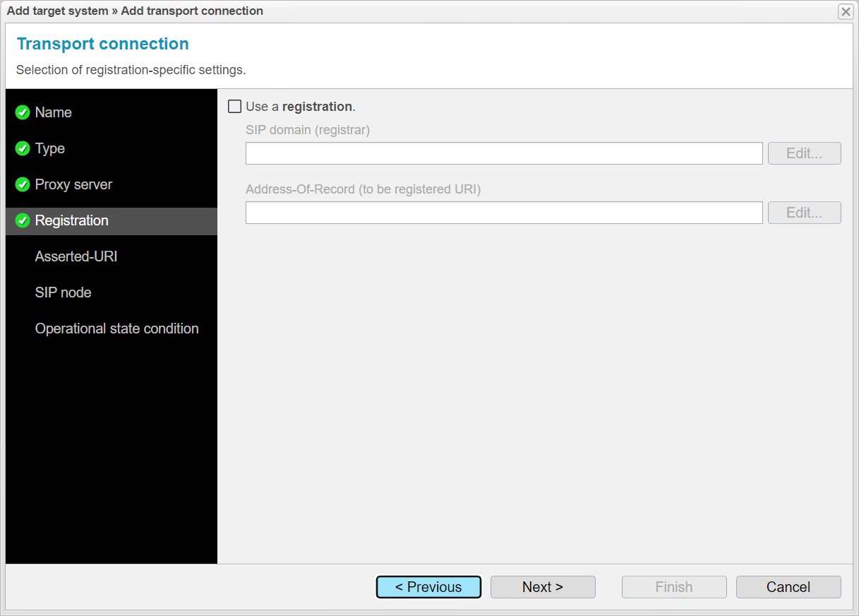
The Registration menu item allows anynode to manage SIP user registrations. This is especially important if anynode acts as a registrar or forwards registration requests to other registrars. We do not need this feature for our example.

Click Next.

Screenshot: anynode – The Software SBC frontend with add target function in the load balancing transport connection of the request router and registration settings. Screenshot: anynode – The Software SBC frontend with add target function in the load balancing transport connection of the request router and registration settings.
anynode – The Software SBC frontend with add target function in the load balancing transport connection of the request router and registration settings.

When integrating another target system, the Asserted URI ensures that the identity of users and systems is transmitted and verified correctly and reliably. We do not need this feature for our example.

Click Next.

Screenshot: anynode – The Software SBC frontend with add target function in the load balancing transport connection of the SIP proxy load balancer and Asserted-URI settings. Screenshot: anynode – The Software SBC frontend with add target function in the load balancing transport connection of the SIP proxy load balancer and Asserted-URI settings.
anynode – The Software SBC frontend with add target function in the load balancing transport connection of the request router and Asserted-URI settings.

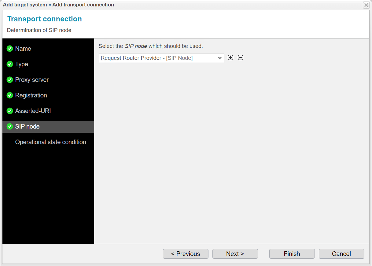
Under SIP Node, select the existing Request Router for the provider, as it will use the new transport connection to also distribute calls to the third target system.

Click Next.

Screenshot: anynode – The Software SBC frontend with add target function in the load balancing transport connection of the request router and SIP node settings. Screenshot: anynode – The Software SBC frontend with add target function in the load balancing transport connection of the request router and SIP node settings.
anynode – The Software SBC frontend with add target function in the load balancing transport connection of the request router and SIP node settings.

The Operational State Condition menu item allows for continuous monitoring of the status of anynode target systems. anynode can determine if a target system is in Maintenance Mode or not. This information is crucial to ensure that SIP messages are only forwarded to functioning target systems. We do not need this feature for our example and can complete the wizard.
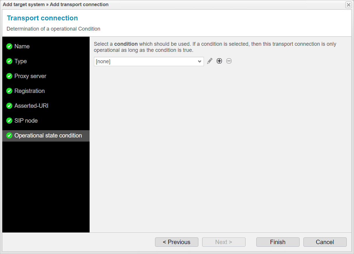
Screenshot: anynode – The Software SBC frontend with add target function in the load balancing transport connection of the request router and operational state condition settings. Screenshot: anynode – The Software SBC frontend with add target function in the load balancing transport connection of the request router and operational state condition settings.
anynode – The Software SBC frontend with add target function in the load balancing transport connection of the request router and operational state condition settings.

Click Finish.

You now have the option to review and adjust the load balancing settings described earlier.

Click Ok.

Screenshot: anynode – The Software SBC frontend with add target function in the request router transport connection of the SIP proxy load balancer and further target system options. Screenshot: anynode – The Software SBC frontend with add target function in the request router transport connection of the SIP proxy load balancer and further target system options.
anynode – The Software SBC frontend with add target function in the request router transport connection of the request router and further target system options.

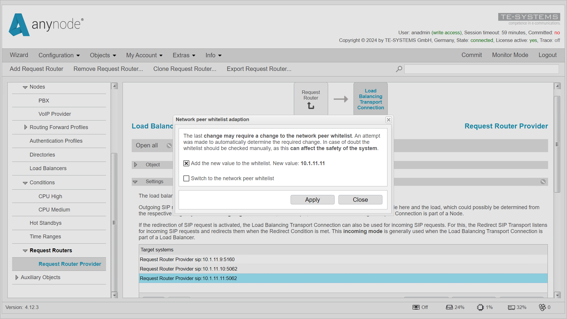
The third anynode target system is now listed under Target Systems. If the new target system is not yet on the whitelist, anynode will notify you with a message.

Confirm the entry in the list with Apply.

Remember to finalize the changes by clicking Commit.

Screenshot: anynode – The Software SBC frontend showing the 'Add Target' function in the load balancing transport connection of the request router, with a third target added. Screenshot: anynode – The Software SBC frontend showing the 'Add Target' function in the load balancing transport connection of the request router, with a third target added.
anynode – The Software SBC frontend showing the 'Add Target' function in the load balancing transport connection of the request router, with a third target added.

Congratulations, you have reached the end of this tutorial and learned everything important about the Request Router.