
Add Request Router
In this chapter, we demonstrate how to set up a request router for the provider node within an existing node configuration that includes a PBX and a VoIP provider. One target system is located on the local anynode instance, while the second target system, with the identical node configuration, resides on a different anynode instance.
Begin in .
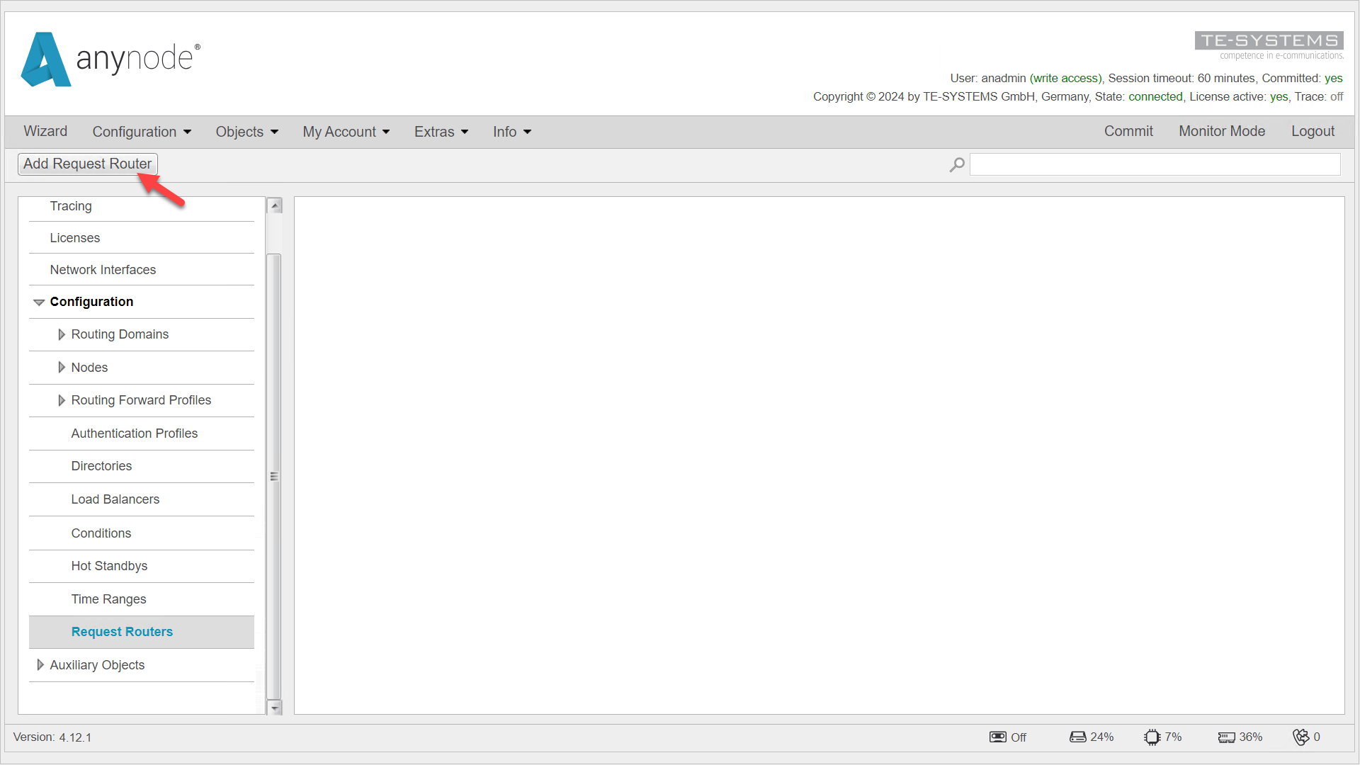
In the left menu under Configuration, navigate to Request Router. Click on at the top.
We will now configure the Request Router for the VoIP provider. The Request Router Assistant will guide you through the configuration in a few steps.
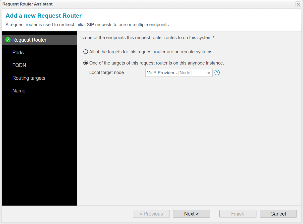
In the Request Router settings, you can choose whether the local target nodes for this Request Router are only on remote systems or if one of the target nodes is on this anynode instance. In our example, the local target node from the VoIP provider is also on the local anynode instance. Use the top option if all target nodes are on remote systems.
Click .
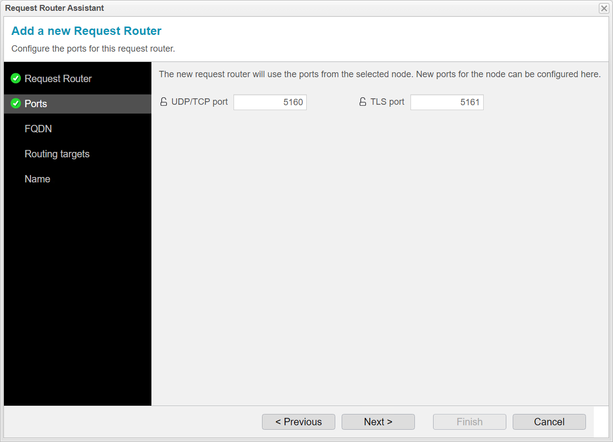
If a local target node is selected, the Request Router Assistant will adopt the port settings from the node for the Request Router. In our example, the port settings are taken from the local VoIP provider node, which uses ports 5060 and 5061. These ports are where the provider sends the INVITE requests.
Since the Request Router now uses these ports, the Request Router Assistant must assign new ports to the provider node. The assistant will suggest new ports with an open lock icon .
Enter the new ports where the VoIP provider will now listen. The Request Router will later forward the INVITE requests to these ports.
When setting up multiple Request Routers, it’s advisable for better organization to increase the original port numbers by a scheme of 100. This is especially useful when you are configuring several Request Routers.
Provider ports previously: 5060/5061
Now, Request Router uses: 5060/5061
Therefore, new Provider ports are: 5160/5161
Click .
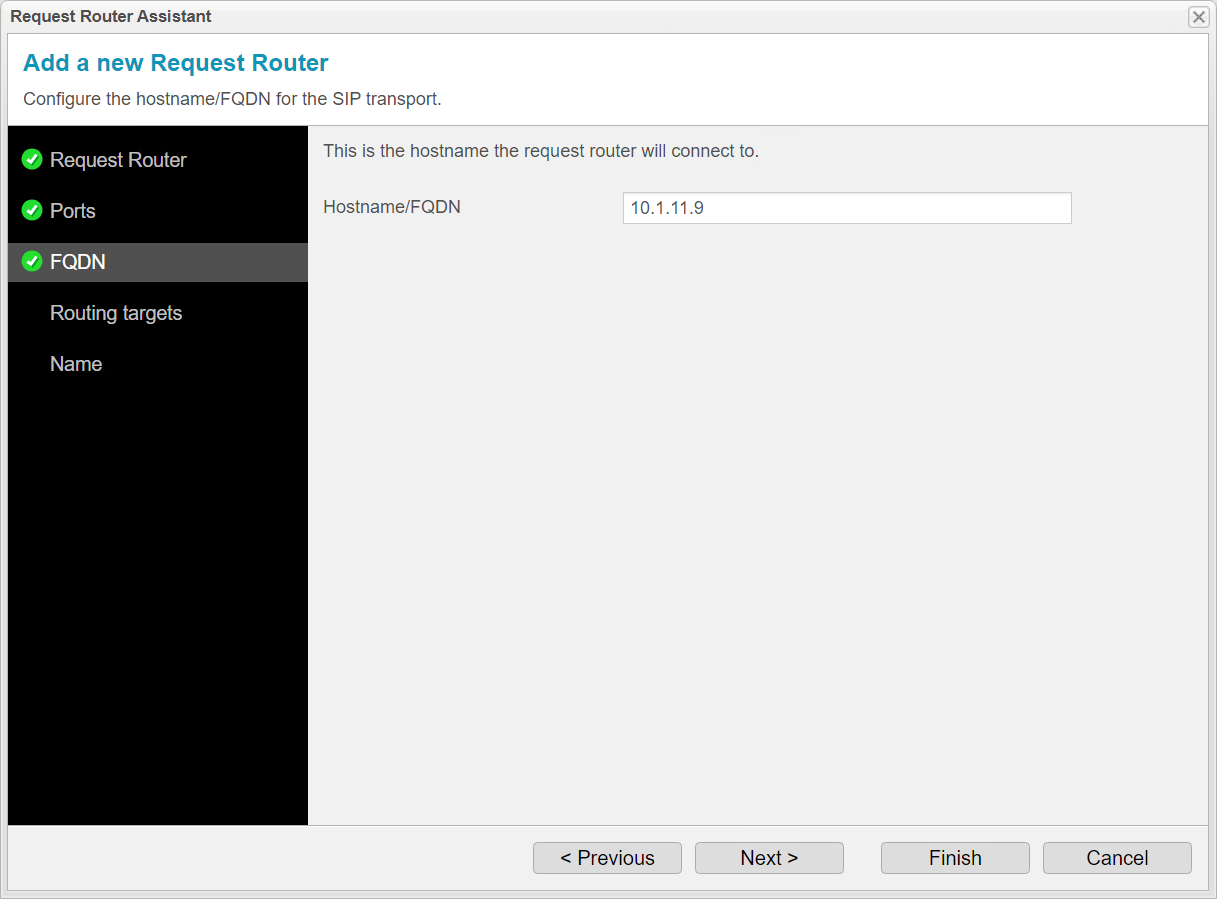
For FQDN, enter the hostname where the local provider node listens. In our example, this is the IP address of the network controller of the local provider node. The Request Router sends incoming calls to this node.
The hostname or IP from this step, along with the port configuration from the previous step, will be used to create an entry for the local node in the routing targets in the next step.
Click .
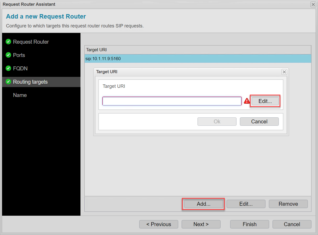
In the Routing Targets section, the assistant has automatically added the first anynode target system to which the calls will be distributed, which is our local anynode system. From the port step, the assistant has entered the port, and from the Hostname/FQDN step, the hostname or IP address has been taken. Now, we want to add our second anynode target system for the Request Router to distribute calls. It’s also possible to use more than two target systems for call distribution.
Click . Click to access additional input options.
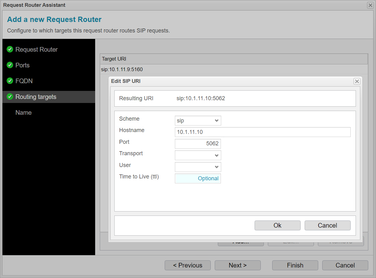
For Hostname, enter the IP address of the second anynode instance.
Use the port configured on the second anynode system for the corresponding node. If the second anynode contains a replicated configuration of this anynode, you must set the same port here that you configured for the node in the previous step.
The provider node on the second anynode system listens on port 5062, so we enter port 5062 here.
Click . Click again to return to the overview of target systems.
Click .
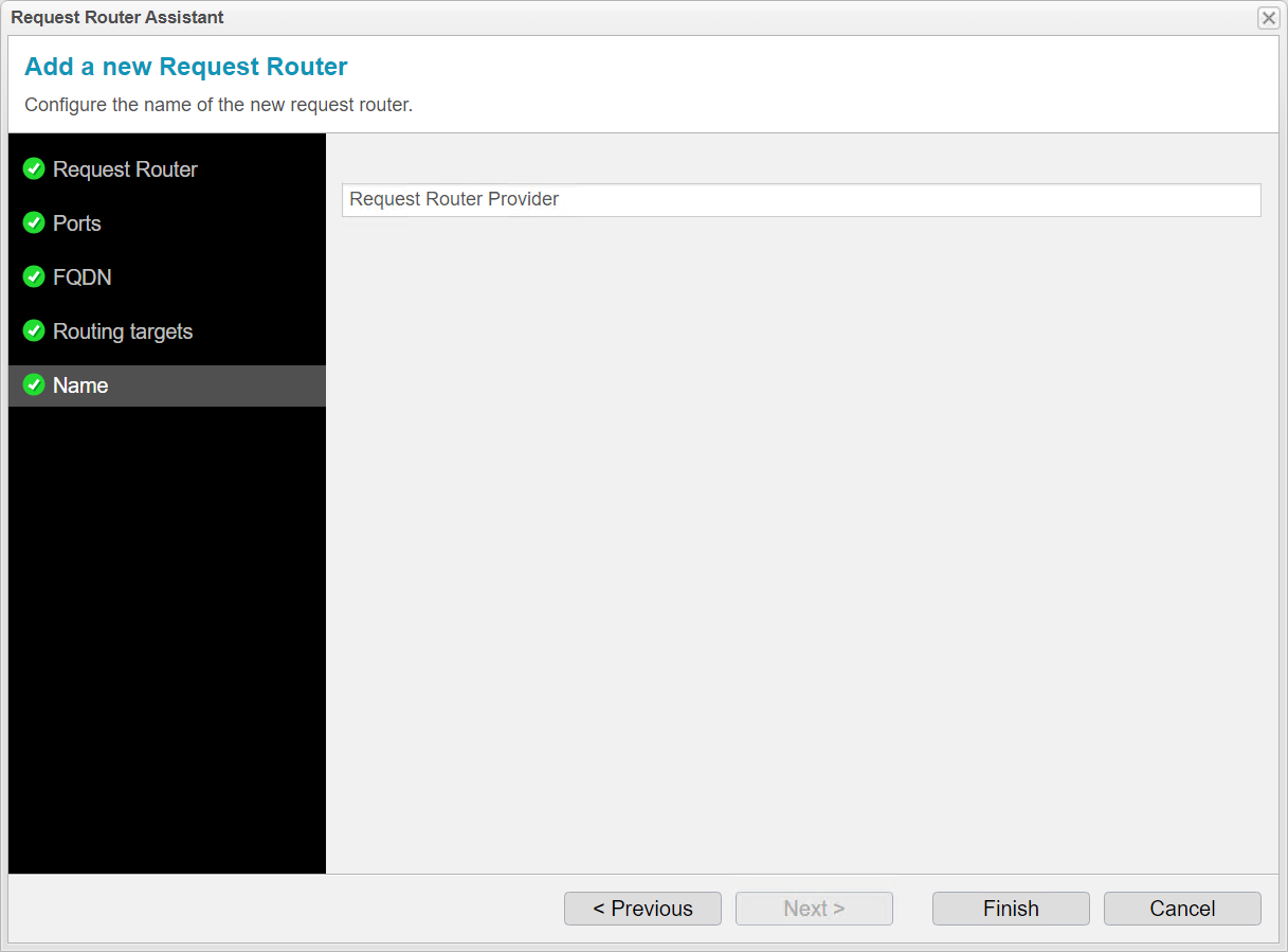
For Name, you can enter any name for the Request Router. The assistant suggests a name. We recommend modifying the name to make it clear that it is the Request Router for the provider.
Click to complete the assistant.
Click on .
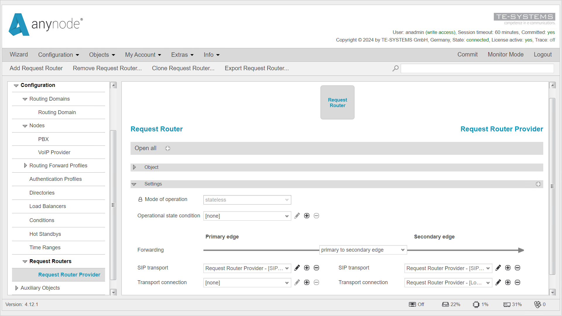
You will now receive an overview of the Request Router settings. The assistant has already configured all the settings.
The Incoming edge SIP transport is the main interface of the Request Router that handles incoming SIP traffic. It is the primary connection point for SIP signaling and the initial recipient of the first INVITE, before it is routed to either the first or second anynode system, or additional anynode systems. The forwarding then occurs through the Outgoing edge SIP transport, where call distribution to the anynode instances takes place.
The target systems to which the first INVITE of an incoming call is distributed are entered in the Transport connection in the Secondary Edge by the assistant.
The Request Router does not modify the information in the contact header but forwards the packet with the information to the node. The node then no longer communicates with the Request Router but directly with the calling endpoint.
Please make sure to review the Failover Between Target Systems chapter to optimize the configuration with a Failover.