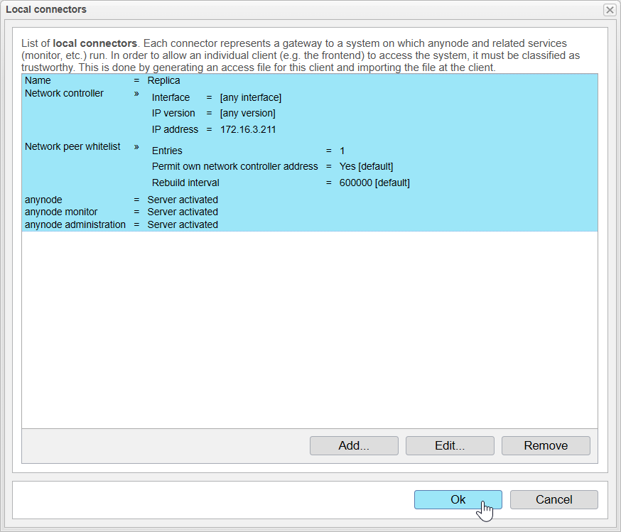
Add Local Backend Connector on Standby System
Up to this point, you have successfully installed two anynode systems and established a configuration on the primary anynode which will be later replicated to the standby system. Now, we will focus on configuring the standby system to allow the primary anynode instance to connect and manage it.
This chapter will guide you through the necessary steps to set up a Local Backend Connector on the Standby System, which is essential for linking the two anynode instances in a high availability setup.
To begin, access the frontend of the standby anynode system. You can reach this interface via the Web Connector that was established during the installation process. If you need more details on accessing the frontend, please refer to the Installation and Maintenance Technote.
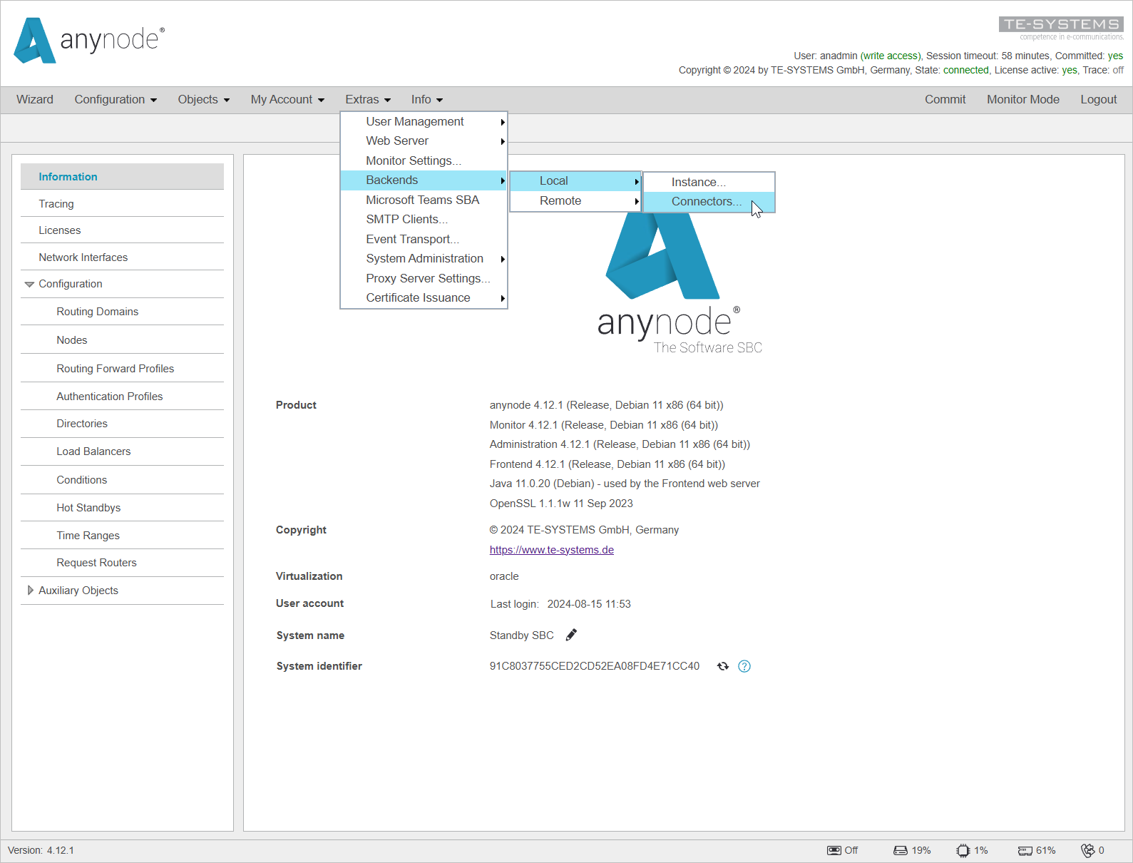
Once you are in the frontend of the standby anynode, navigate to the Extras menu. From there, go to Backends, select Local, and then choose connectors.
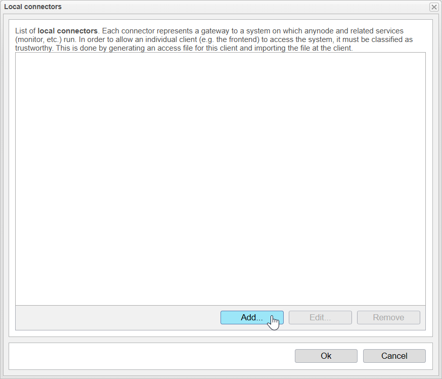
A list will now open displaying all the configured Local Connectors.
Since our second system is entirely new, there are no entries yet.
By clicking , we enter the setup process that opens the Connector Assistant to create the Local Connector.
Connector Assistant
Purpose
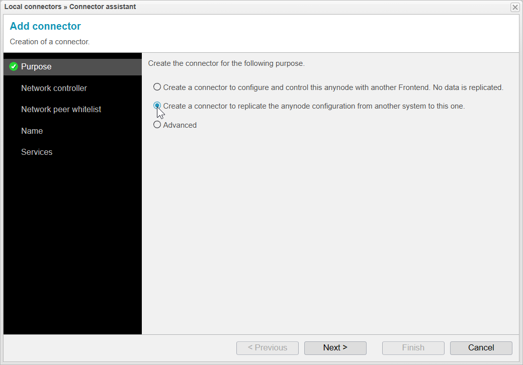
Firstly, we select the second option for this scenario: Create a connector to replicate the anynode configuration from another system to this one.
The first option, Create a connector to configure and control this anynode with another Frontend. No data is replicated, is useful if you want to connect multiple anynodes without replication, but this is not part of our current scenario.
It's important to note that Hot Standby can be used both with and without replication.
Click to proceed to the next step.
Network Controller
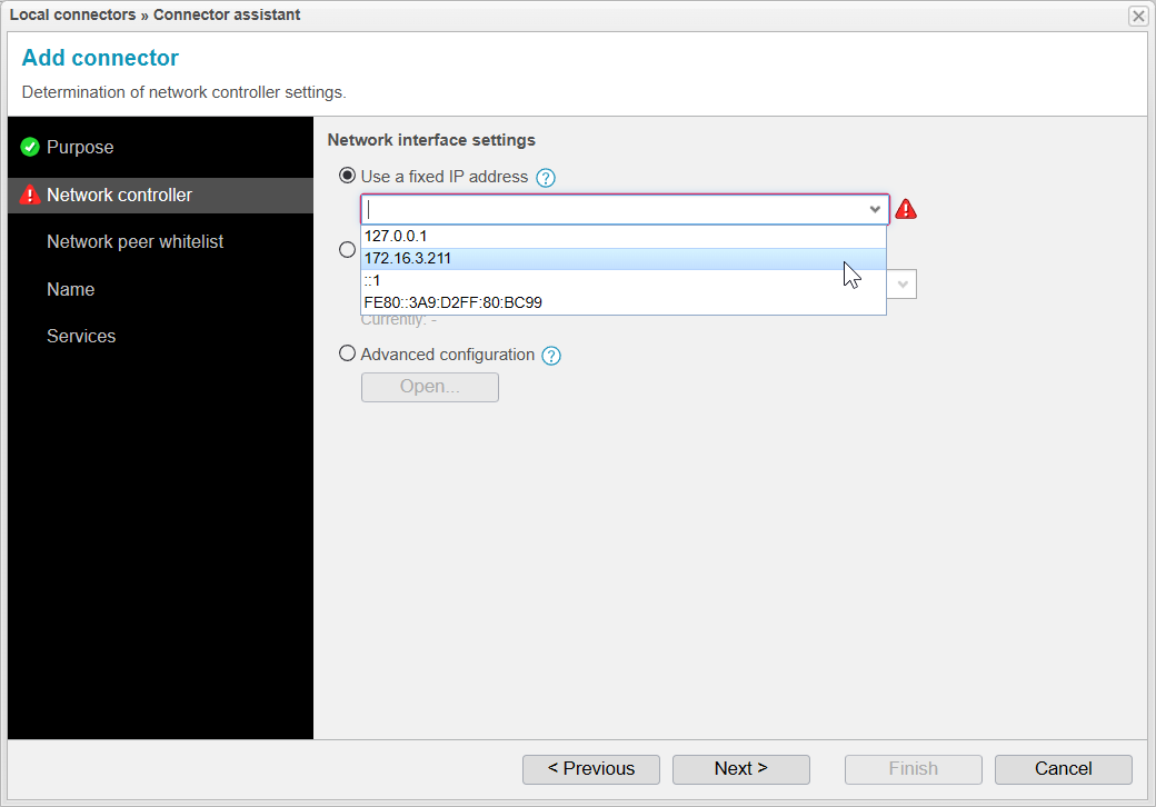
In the next step, we will select which IP address will be used for the Local Connector.
This IP address will later be used to listen for packets from the Master on ports 12100 (anynode), 12102 (anynode monitor), and 12106 (anynode administration).
We recommend choosing the Use a fixed IP address option and setting a fixed IP address. This address must always be available on the system and should not change. It's crucial that the primary anynode can reliably reach each standby anynode using this address.
The Use an interface’s address option is not recommended, as the IP address might change dynamically if an interface address is selected, which could lead to connection issues between the anynode instances.
Click to proceed to the next step.
Network Peer Whitelist
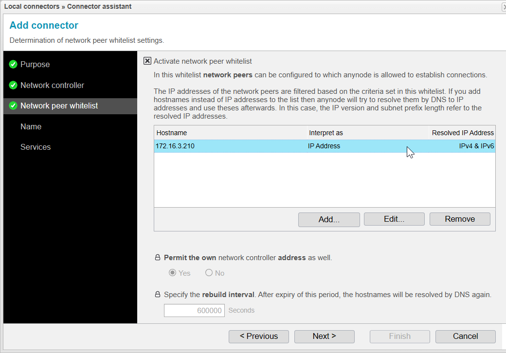
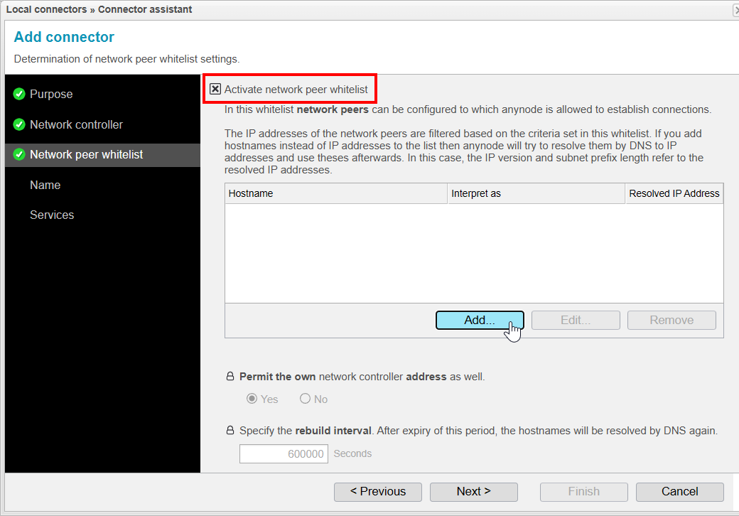
With the Network Peer Whitelist, you can restrict which IP addresses are allowed to access the Local Connector of this system. In our case, the address can be accessed externally, so we want to restrict access so that only the other anynode can connect to the Local Connector.
The option Permit the own network controller address as well ensures that the IP address configured in the previous step is also included in the allowed addresses. However, in this scenario, it is not relevant since the other anynode should be on a different machine with a different IP address.
The setting Specify the rebuild interval. After expiry of this period, the hostnames will be resolved by DNS again. is relevant if hostnames are entered into the whitelist that need to be resolved by anynode. This interval determines how long it will take before the DNS cache is refreshed. By default, this is set to 600,000 seconds (10,000 hours).
The DNS cache will always be refreshed when anynode is restarted.
Check the box if you wish to activate the Network Peer Whitelist.
Then Click to create a new entry in the Network Peer Whitelist

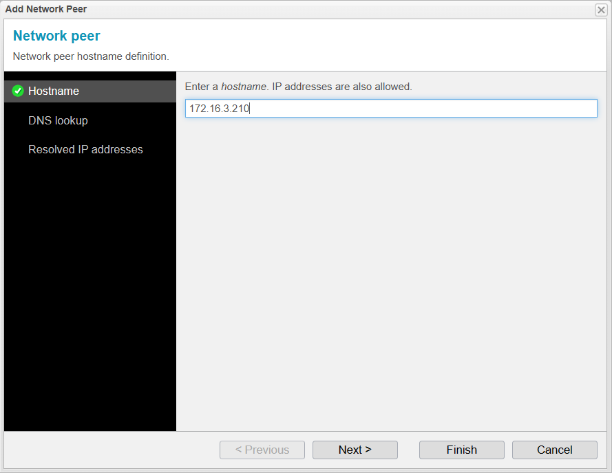
Add Network Peer / Hostname
A new assistant now opens to allow you to enter Network Peers. Here, you can enter both hostnames and IP addresses, as well as SRV records.
The specific settings for these can be found in the next step, DNS Lookup. In this step, we will enter the IP address of the Primary system to grant it access to the Standby system.
Click to proceed to the next step.
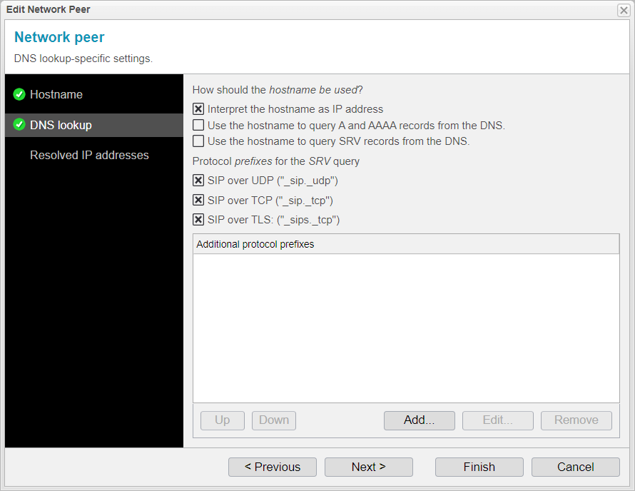
Add Network Peer / DNS Lookup
In the DNS Lookup step, you typically don't need to make any adjustments, as the settings are automatically configured based on the hostname or IP address entered in the previous step.
You'll notice that the system has recognized the entry as an IP address, so a checkmark has been placed next to Interpret the hostname as IP address.
The other settings will adjust accordingly if A, AAAA, or SRV records are used.
If needed, you can restrict the use of hostnames or set additional SRV query prefixes, but this is usually not necessary and depends on your network environment.
Click to proceed to the next step.
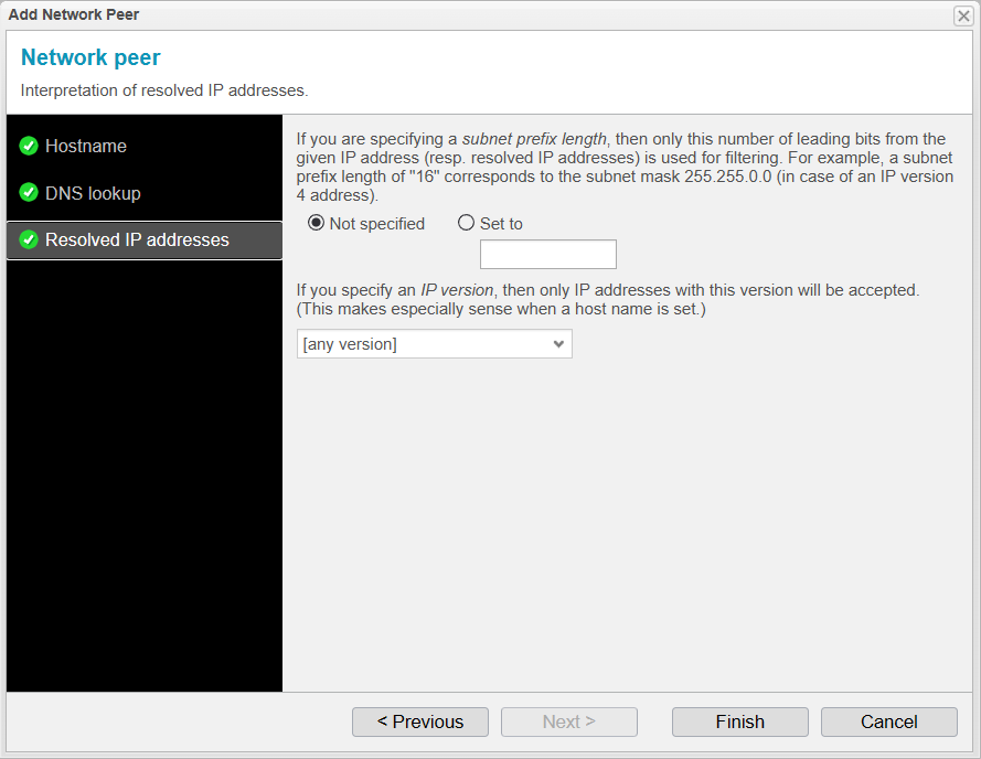
Add Network Peer / Resolved IP Addresses
Now, you can specify whether you want a particular IP address or to use an entire range within a subnet. To do this, you would need to use the appropriate subnet mask that covers the desired network. This is particularly useful if you've entered a fixed IP address as the hostname.
You can also specify an IP version, which means you can choose to accept packets only from an IPv4 or IPv6 address. This option is mainly relevant when entering hostnames. If an IP address has been entered, you've already specified it as either IPv4 or IPv6.
Since we have entered an IPv4 address for the hostname and only want to accept packets from this specific IP address, we leave the Subnet setting on Not specified. The entered address is an IPv4 address, so there's no need to make any further specifications, and we leave the IP version setting on [any version].
Click to complete the setup process for adding a Network Peer.
Network Peer Whitelist
Back on the main page of the Connector Assistant we will now see a new entry in the Network Peer Whitelist. This entry summarizes the settings you have configured:
-
The setting from the Hostname step, where we entered an IP address in our case.
-
The setting from the DNS Lookup step, where it was determined that the hostname should be interpreted as an IP address.
-
The setting from the Resolved IP Addresses step, where we kept the default setting with no subnet mask specified and accepted all IP versions.
Click to proceed.
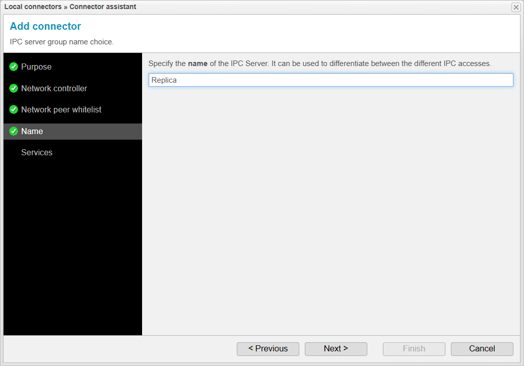
Name
In this step, you will set the name that the second anynode will be displayed with in several areas:
-
The name of the IPC Server.
-
The name of the exported .xzbackend file.
-
The name in the Remote Backend list on the Master anynode.
-
The name in the Backend Selector on the Master anynode.
Since this name will be used in many places, it is important to choose a name that is easily recognizable, especially if you plan to replicate to more than one anynode.
In our case, we will keep the default name Replica, as we are only replicating our configuration to a single anynode.
Click to proceed to the next step.
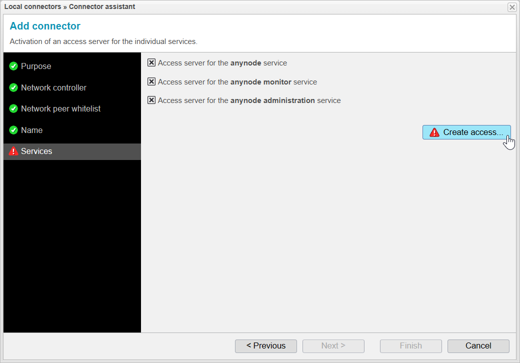
Services
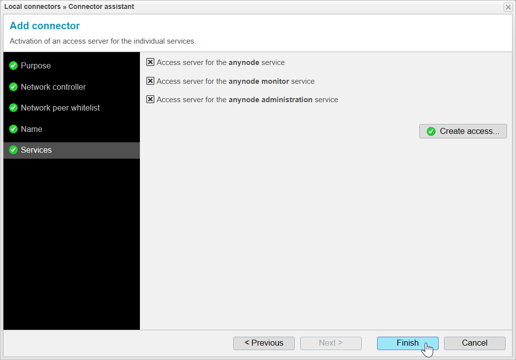
When you reach the Services step, anynode will first generate certificates and private keys and activate the access server.
The public keys corresponding to these private keys will be included in the .xzbackend file, which we will
export later.
Once the generation is complete, the button should become available.
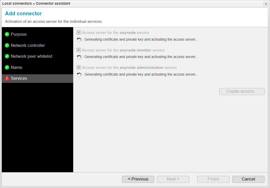

The certificates and private keys have now been successfully generated, and the access servers have been activated. You can confirm this by seeing that all three points are checked.
At this stage, you could choose to disable certain services, making them controllable or viewable by the other anynode. However, this is not recommended, and we will not do this in our current scenario.
Click on to move on.
Access & Export Assistant
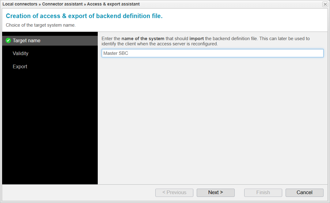
Target Name
Now the Access & Export Assistant will open. In this assistant, a few more parameters will
be set before exporting the .xzbackend file, which will later need to be imported into the Master anynode.
In the Target Name step, you specify the name of the system that will import the file. This name will later be included in the subject of the certificate that the Master presents to the Standby. This is particularly relevant if multiple anynode instances need to access this single anynode. However, in our current scenario, this is not the case.
Click to proceed to the next step.
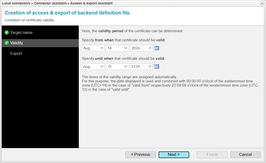
Validity
In the Validity step, you determine how long the certificates that anynode generates for the connection between the two anynodes will be valid. By default, the certificates are set to be valid for 100 years. We will keep the default 100 years, as there is usually no reason to restrict the validity period.
Click to proceed to the next step.
Export
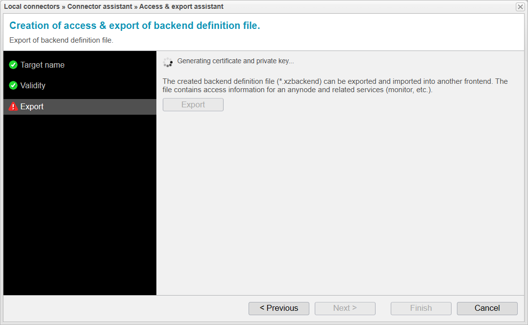
In the Export step, anynode generates the certificate and private key for the Master system.
It then writes these, along with other connection data, into the .xzbackend file.
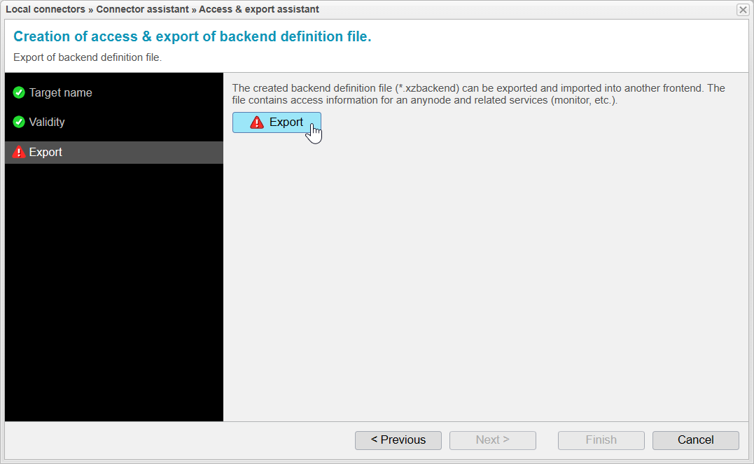
Once anynode finishes generating the necessary files, the Export button will become available.
By clicking , the Replica.xzbackend file will be downloaded. The
file name is derived from the name chosen for the IPC Server.
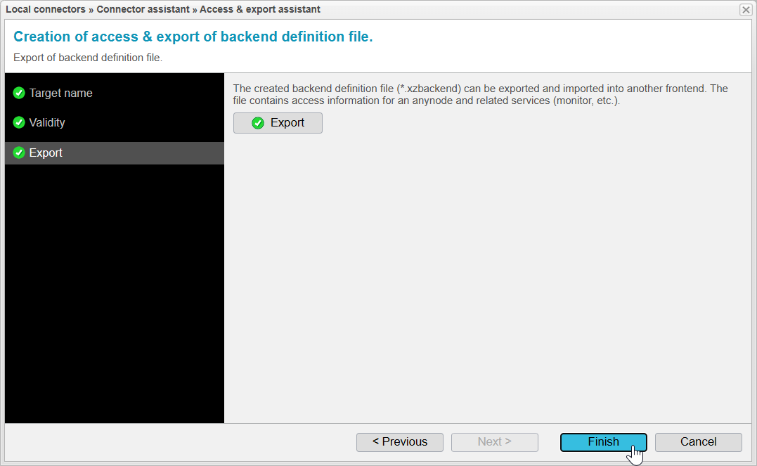
After the file is downloaded, the button will display a green checkmark
and the button will become available.
You can close the wizard by clicking .
Do not click Cancel unless you intend to cancel the entire process.
Services
After downloading the replica.xzbackend file, you can close the Connector Assistant by
clicking .
Local Connectors List
After closing the assistant, the newly created Local Connector will now appear in the Local Connectors List.
To finalize the configuration, confirm this list by clicking .
In the next subchapter Add Remote Backend Instance
on Primary System, we will move to the Master system to import the replica.xzbackend file and complete the
remaining configuration steps there.
