Manual Handover and Recovery
In this chapter, we will cover how to manually perform a handover and recovery between the Main System and the Standby System in a Hot Standby Setup.
-
We start by initiating a handover to transition the active role from the Main System to the Standby System. During this process, there may be a brief moment where both systems are in Standby mode as the Main System waits for confirmation from the Standby System to take over.
-
After a successful handover, the Main System will move to STANDBY status, and the Standby System will become ACTIVE. This status change can be observed in Monitor Mode, where the network controllers and conditions indicate which system is currently active.
-
You can then manually recover to revert to the original state, where the Main System returns to active status and the Standby System goes back to Standby. This ensures both systems are correctly synchronized and ready for operation.
We will now perform a Hand over, which will transition the currently active Main System into Standby mode and activate the Standby System.
To do this, click on handover.
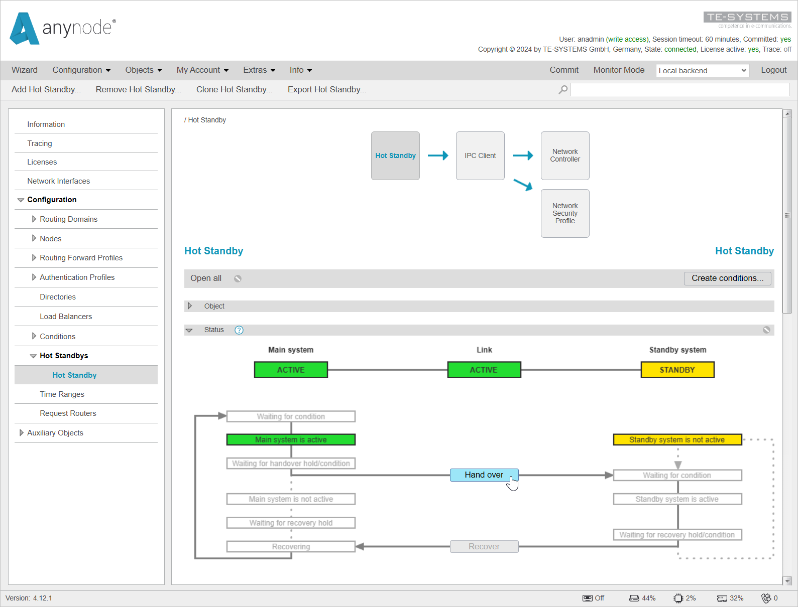

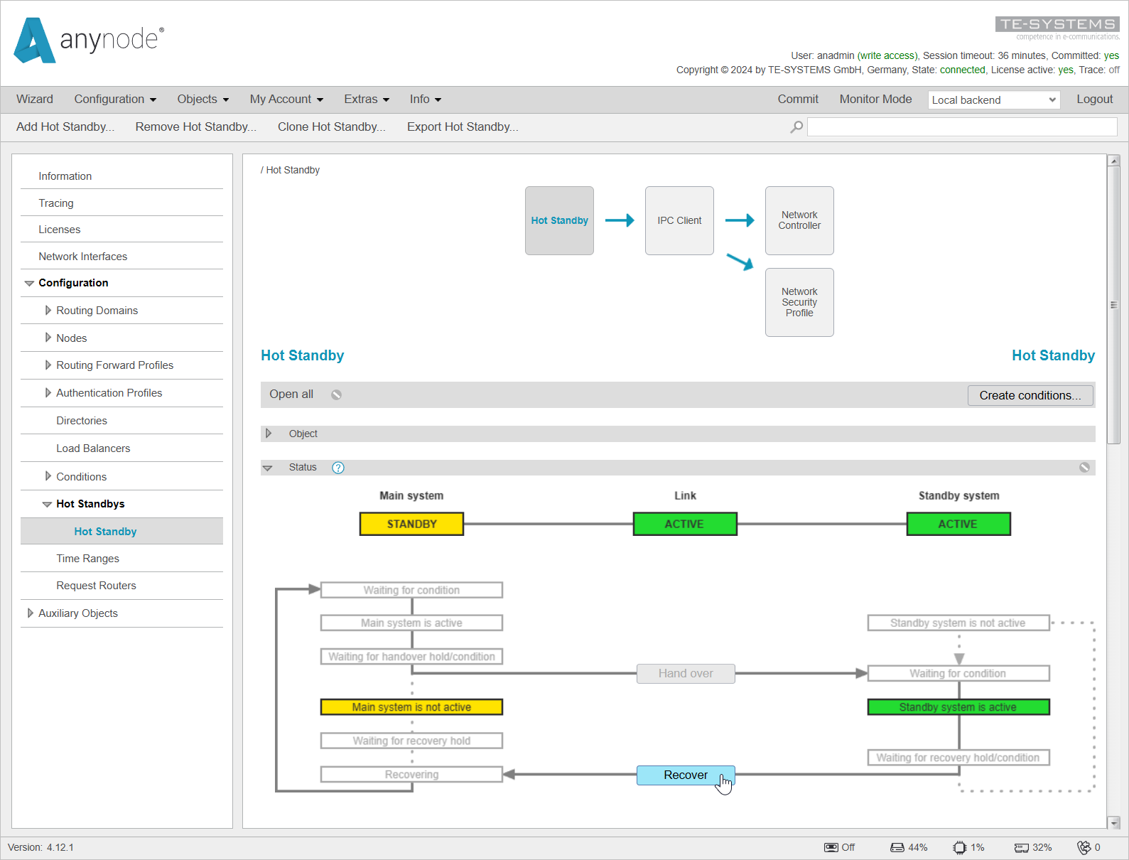
There may be a very brief moment when both systems are in Standby. This is the moment when the Main System relinquishes its active status. Normally, the state shown in the screenshot is not visible because the handover happens very quickly.
You can see on the Main System side that it is currently in the state. It is now waiting, based on the set timer, for a response from the Standby System that it has activated.
This mechanism allows the Main System to become active again if it does not receive timely feedback from the Standby System. The timer is typically set to 15 seconds.
Even in this state, you can already click on the button to have the Main System reassume the ACTIVE status.
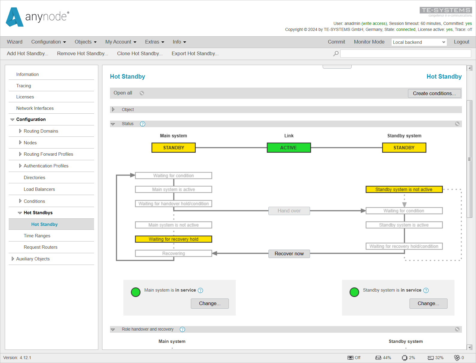

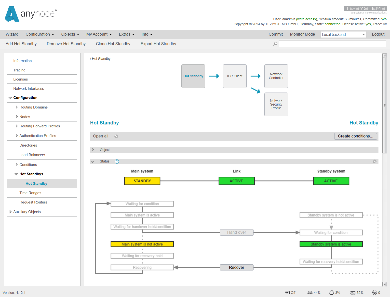
After a successful Hand over, the Main System is now in standby status, and the Standby System is active .
On the Main System side, you can now see that the status is displayed.

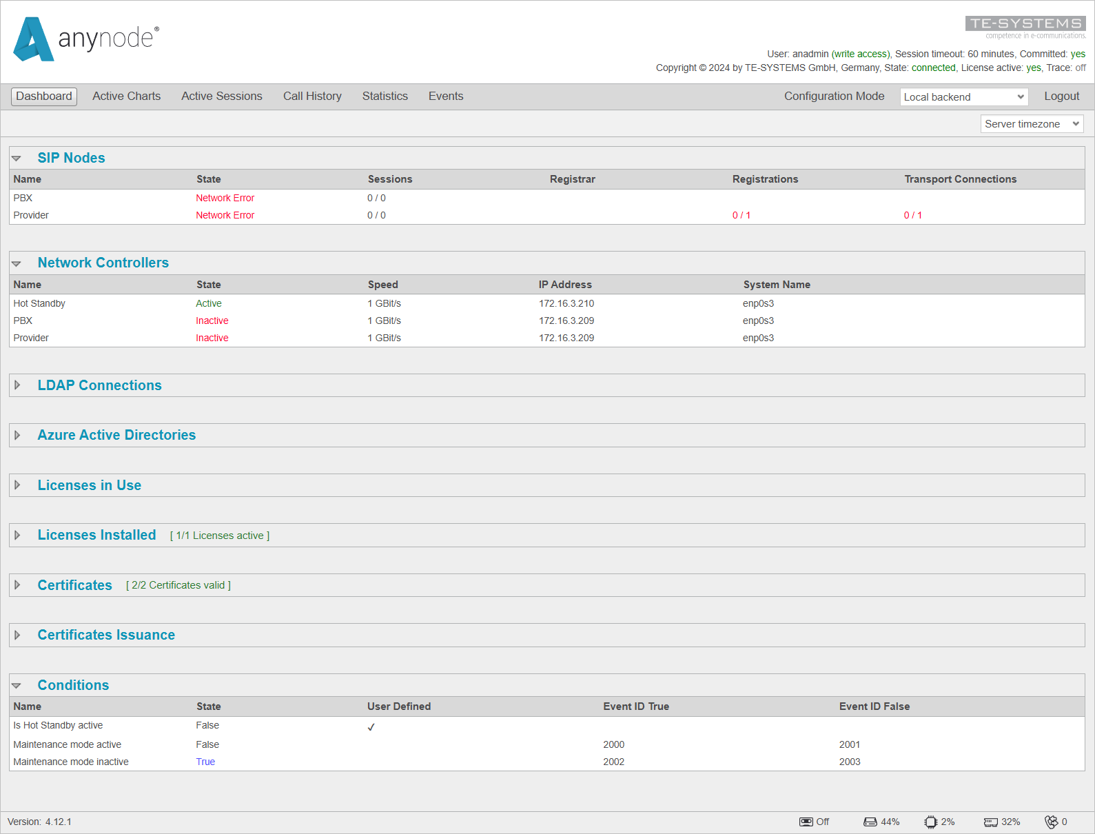
On the Local Backend in Monitor Mode, the Dashboard now shows that both PBX and Provider display a Network Error because the IP address is no longer present on the Local Backend.
This can also be observed in the Network Controllers section, where the State is now shown as inactive .
Additionally, you can see that the condition is set to false .
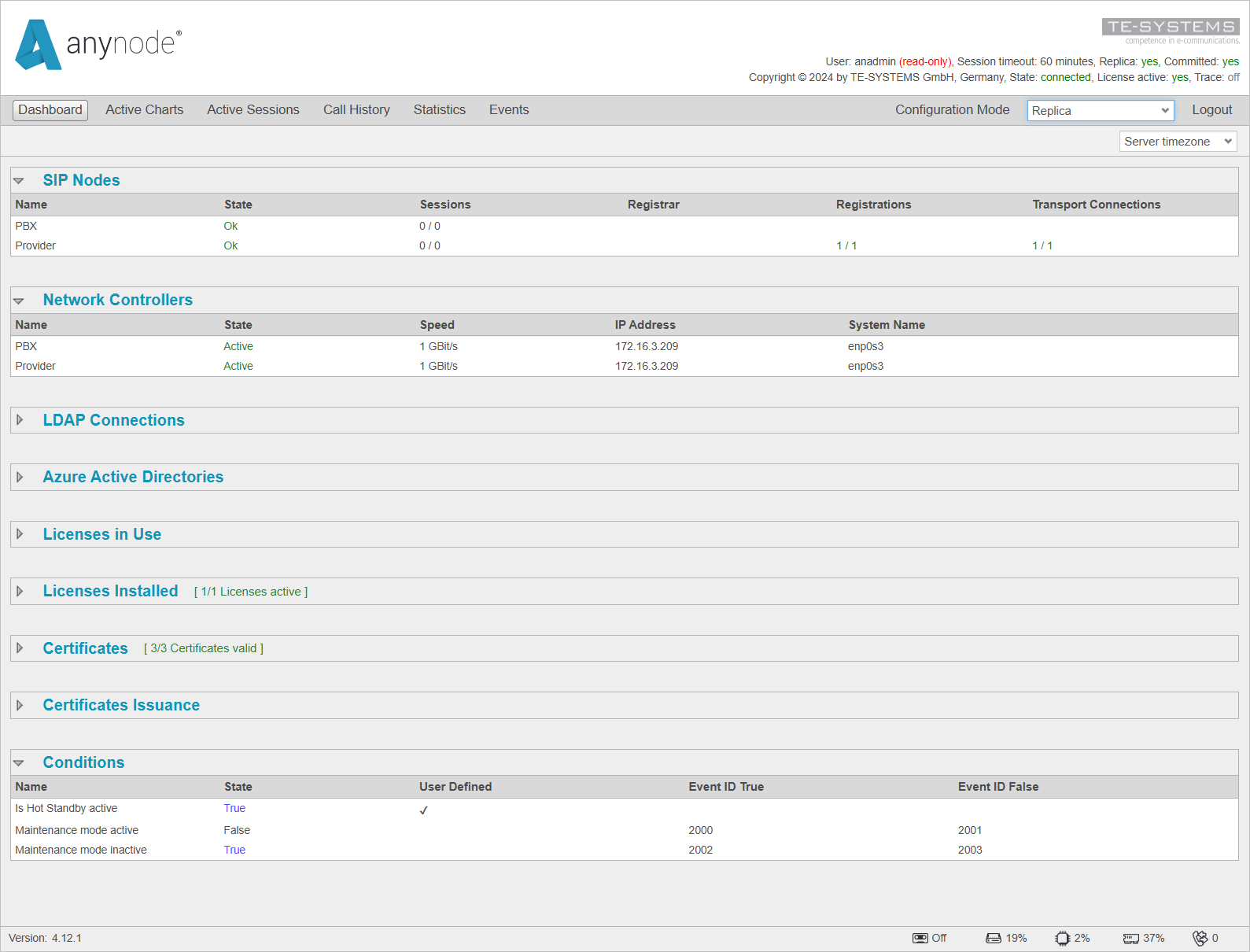
On the Replica in Monitor Mode, the Dashboard now shows ok for both PBX and Provider since the IP address is no longer on the Local Backend but is now present on the Replica.
This is also reflected in the Network Controllers, where the State is now displayed as active .
Additionally, you can see that the condition is set to true .
You can now return to the original state by clicking on recover .
This will switch the Main System back to the active state and the Standby System back to standby .
